 wwaterjet
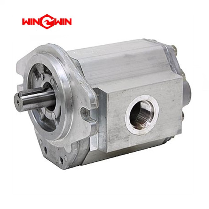

Table 12-7 Hydraulic Pump Assembly 20498668 | |||
Item | Part Number | Description | Quantity |
1 | 05045505 | Piston Pump | 1 |
2 | 20498626 | Gear Pump | 1 |
3 | 05139720 | O-Ring, 85MM x 3MM | 1 |
4 | 49883580 | Flat Washer, M10 | 2 |
5 | 10064715 | Lock Washer, M10 | 2 |
6 | 05037593 | Socket Head Screw, M10 x 1.50 x 25MM | 2 |
7 | 05048780 | Split Flange Kit, 2.0 | 1 |
8 | 05048806 | Adapter, Flange/Hose, 2.0 x 2.0 | 1 |
The hydraulic pump assembly in a waterjet system is a vital component that provides the hydraulic power needed to drive the intensifier pump,
which in turn pressurizes the water for cutting. This assembly must be robust and reliable to handle the high pressures and continuous operation required in waterjet cutting.
Key Components of a Hydraulic Pump Assembly
1. Hydraulic Pump: The core component that converts mechanical energy into hydraulic energy. It can be a piston pump, vane pump, or gear pump, depending on the system's design.
2. Electric Motor: Drives the hydraulic pump. The power and speed of the motor are selected based on the requirements of the hydraulic system.
3. Coupling: Connects the motor to the pump, allowing for the transfer of power. It must be aligned correctly to avoid excessive wear.
4. Mounting Frame: Provides a stable base for the pump and motor assembly. It must be robust to handle the vibration and weight of the components.
5. Hydraulic Reservoir: Stores the hydraulic fluid and aids in cooling and filtering. It includes a filler cap, breather, and drain plug.
6. Filters: Remove contaminants from the hydraulic fluid. They can be located in the reservoir, suction line, or return line.
7. Heat Exchanger: Maintains the hydraulic fluid at an optimal temperature. This can be an air-cooled or water-cooled unit.
8. Pressure Relief Valve: Protects the system from overpressure by diverting excess fluid back to the reservoir.
9. Control Valves: Regulate the flow and pressure of hydraulic fluid within the system. They can be manual or electronically controlled.
10. Pressure Gauges: Monitor the hydraulic pressure to ensure it remains within the desired range.
11. Hoses and Fittings: High-pressure hoses and fittings transport hydraulic fluid between the pump, valves, and other components.
They must be rated for the system's operating pressure.
12. Accumulators: Store hydraulic energy and help in maintaining steady pressure by compensating for pressure fluctuations.
Maintenance Tips
Regular Inspections: Check for leaks, wear, and damage in hoses, fittings, and other components.
Fluid Maintenance: Regularly check and replace hydraulic fluid according to the manufacturer's recommendations. Ensure the fluid is clean and at the correct level.
Filter Replacement: Replace filters periodically to maintain fluid cleanliness and protect the system from contaminants.
Cooling System Maintenance: Ensure the heat exchanger is functioning correctly and not obstructed. Check coolant levels if applicable.
Check Pressure Settings: Verify that pressure relief valves and control valves are set to the correct pressures to prevent system damage.
Pump and Motor Alignment: Ensure the coupling and alignment between the pump and motor are correct to avoid excessive wear and vibration.
Lubrication: Ensure that all moving parts are adequately lubricated to reduce friction and wear.
Troubleshooting Common Issues
Overheating: Check the heat exchanger/cooler, ensure proper fluid levels, and verify that the system is not operating beyond its capacity.
Low Pressure: Inspect for leaks, check fluid levels, and ensure the pump is functioning correctly. Replace worn components as needed.
Fluid Contamination: Regularly replace filters and ensure the reservoir is sealed correctly. Use high-quality hydraulic fluid.
Noisy Operation: Could indicate air in the system, low fluid levels, or worn components. Bleed the system to remove air and check for proper fluid levels and component condition.
Vibration and Noise: Excessive vibration can lead to premature wear and failure. Ensure all support brackets and clamps are secure and that the system is properly aligned.
Conclusion
The hydraulic pump assembly is crucial for the operation of a waterjet system, providing the necessary power to drive the intensifier pump.
Regular maintenance, proper assembly, and timely troubleshooting of issues are essential for ensuring the longevity and efficiency of the system.


