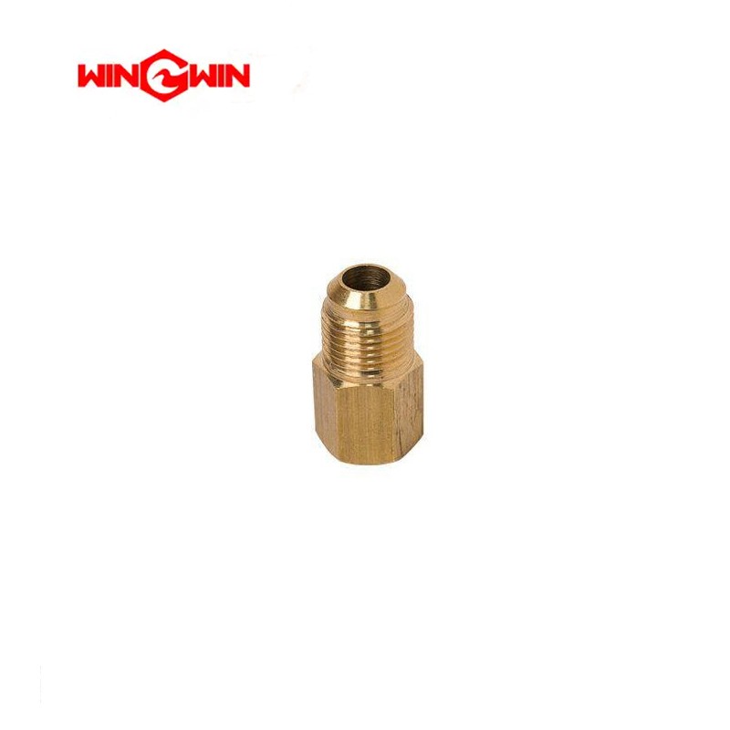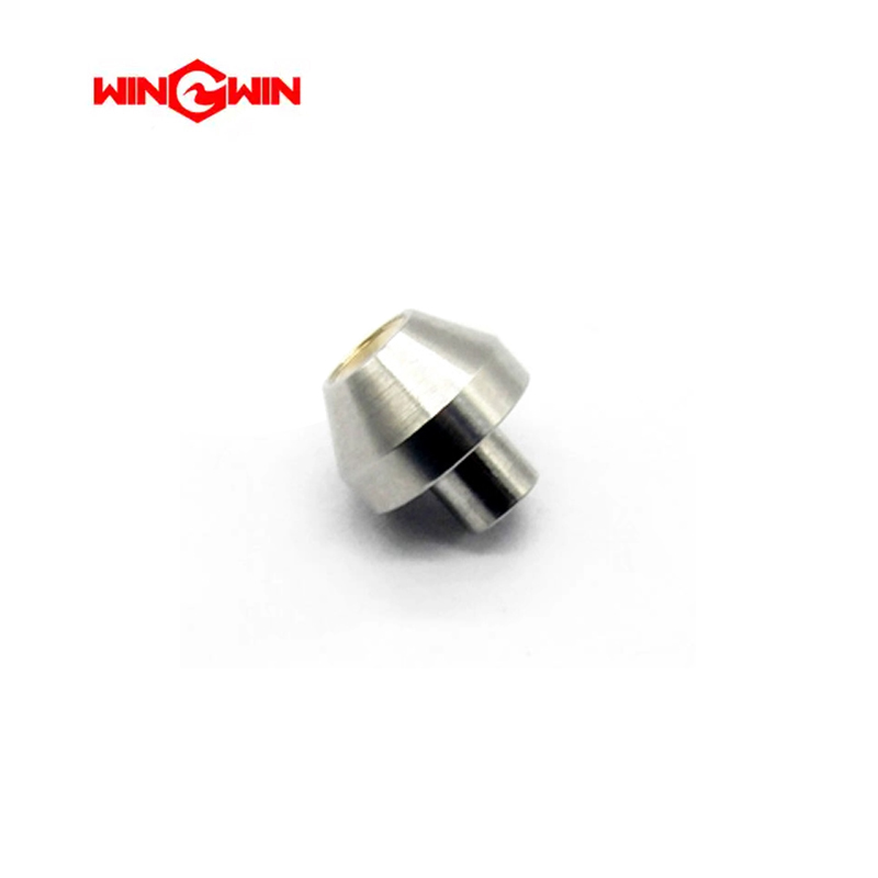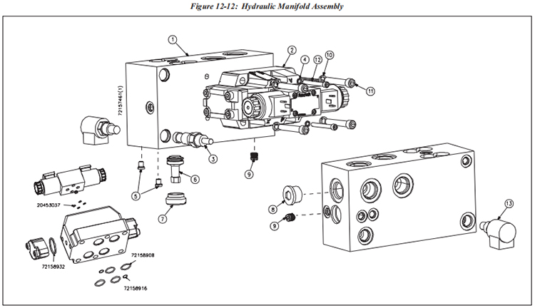
Table 12-12 Hydraulic Manifold Assembly 72157461 | |||
Item | Part Number | Description | Quantity |
1 | 72156430 | Hydraulic Manifold | 1 |
2 | 72157479 | Directional Control Valve | 1 |
3 | 10187060 | Relief Valve Assembly | 1 |
4 | 10069581 | Lock Washer, .25 | 2 |
5 | 05055017 | Plug, ORB, .13 | 2 |
6 | 49889736 | Check Valve Assembly | 1 |
7 | 49889744 | Retainer, Cartridge Valve | 1 |
8 | 05071055 | Plug, ORB, .75 | 1 |
9 | 49889769 | Plug, ORB, .25 | 2 |
10 | 95688743 | Lock Washer, .38 | 4 |
11 | 05041058 | Socket Head Screw, 3/8-16 x 2-1/4 | 4 |
12 | 72157677 | Socket Head Screw, 1/4-20 x 2-1/4 | 2 |
13 | 10185585 | Solenoid Valve | 1 |
The hydraulic manifold assembly in a waterjet system serves as a critical component that distributes hydraulic fluid or water to various parts of the system while allowing control over the flow, pressure, and direction of the fluid. Specifically in a waterjet system, the hydraulic manifold assembly helps regulate and direct the high-pressure water flow required for cutting.
Key elements of a hydraulic manifold assembly in a waterjet system typically include:
1. Manifold Block: This is the primary component, often made of metal (such as aluminum or stainless steel), which contains passages, channels, and ports for the hydraulic fluid or high-pressure water to flow through. The block is designed with precision to ensure proper distribution of the fluid.
2. Valves and Controls: The manifold assembly contains valves, such as directional control valves or flow control valves, that regulate the flow rate, pressure, and direction of the high-pressure water within the system. These valves are often electronically or manually controlled.
3. Ports and Connectors: The manifold assembly includes ports and connectors to link the high-pressure lines, hoses, or tubes to the various components of the waterjet system, such as the high-pressure pump, cutting head, accumulator, and other related parts.
4. Pressure Sensors or Gauges: Some manifold assemblies incorporate pressure sensors or gauges to monitor the pressure levels of the hydraulic fluid or water flow through the system.
5. Filtration and Cooling Elements: To maintain the quality of the hydraulic fluid or water, some manifold assemblies might include filtration components to remove contaminants, as well as elements for cooling the fluid to prevent overheating.
The hydraulic manifold assembly plays a crucial role in the efficient and controlled operation of a waterjet cutting system. It ensures the precise distribution and control of high-pressure water, allowing for accurate cutting while maintaining the integrity and safety of the entire hydraulic system. These assemblies are specifically designed to meet the demanding requirements of waterjet cutting, providing reliability, precision, and control in the operation of the system.
 wwaterjet