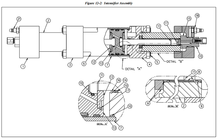
Table 12-2 Intensifier Assembly 20458728 | |||
Item | Part Number | Description | Quantity |
1 | 20458305 | End Cap | 2 |
2 | 20457399 | High Pressure Cylinder | 2 |
3 | 20458299 | End Bell, LH | 1 |
4 | 20458302 | End Bell, RH | 1 |
5 | 20458191 | Tie Rod | 4 |
6 | 20460489 | Hex Nut | 8 |
7 | 20457414 | Hydraulic Cylinder | 1 |
8 | 20458161 | Backup Sleeve | 2 |
9 | 20458773 | Rebuild Kit, High Pressure Seal Assembly | 1 |
20457990 | Seal Buttress | ||
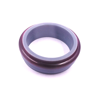
20458113 | High Pressure Seal | ||
20457393 | Seal Hoop | ||
20460108 | O-Ring | ||
10 | 20458797 | Rebuild Kit, Hydraulic Seal Assembly | 1 |
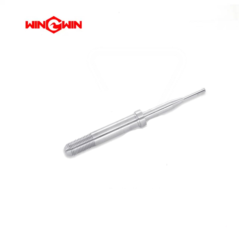
11 | 20457912 | Plunger | 2 |
12 | 20458062 | Plunger Retainer | 2 |
13 | 20458869 | Hydraulic Piston Assembly | 1 |
20457966 | Hydraulic Piston | ||
20458821 | Rebuild Kit, Piston Rings | ||
20460216 | Seal | ||
14 | 20458170 | Spacer, Hydraulic Seal | 2 |
15 | 20458908 | Sealing Head Assembly | 2 |
16 | 20460252 | Snap Ring | 2 |
17 | 05202930 | Snap Ring | 2 |
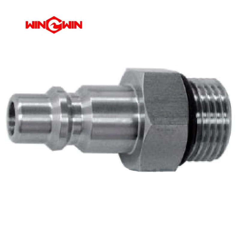
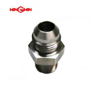
18 | 20457267 | Inlet Water Nipple | 2 |
20457159 | Adapter, Quick Disconnect | ||
20459025 | O-Ring, Quick Disconnect | ||
An intensifier assembly is a specialized device designed to increase the pressure of water for various high-pressure applications.
These applications can range from water jet cutting to high-pressure cleaning and hydraulic systems. Here's an in-depth look at the components,
working principles, and applications of an intensifier assembly:
Components of an Intensifier Assembly
1. Intensifier Pump: The core component that increases the water pressure. It typically consists of a low-pressure piston driving a high-pressure piston.
2. Drive Cylinder: Often powered by hydraulic fluid, this cylinder provides the initial force needed to move the intensifier piston.
3. Water Inlet and Outlet: Ports where water enters at low pressure and exits at high pressure.
4. Control Valves: Regulate the flow of water into and out of the intensifier pump, ensuring precise operation.
5. Accumulator: A high-pressure reservoir that smooths out pressure fluctuations and stores pressurized water for consistent output.
6. Check Valves: Prevent backflow of water, ensuring that high-pressure water flows in the correct direction.
7. Seals and Gaskets: Critical for maintaining pressure integrity and preventing leaks.
8. Cooling System: Often required to dissipate heat generated during the pressurization process.
Working Principle
The working principle of an intensifier assembly is based on hydraulic intensification, where a larger diameter,
low-pressure hydraulic piston drives a smaller diameter, high-pressure water piston. The force applied to the hydraulic piston is transferred to the water piston,
resulting in a higher pressure output.
Applications
1. Water Jet Cutting: Utilizes high-pressure water jets to cut through materials such as metal, stone, and glass with precision.
2. High-Pressure Cleaning: Used in industrial cleaning applications where high-pressure water removes tough contaminants.
Advantages
1. High Efficiency: Capable of generating very high pressures from relatively low input pressures.
2. Versatility: Can be used in a wide range of industrial applications.
3. Precision: Provides precise control over pressure levels, essential for applications like water jet cutting.
Conclusion
An intensifier assembly is a crucial device for generating high-pressure water required in various industrial and technical applications.
Understanding its components, working principles, applications, and maintenance requirements ensures its effective and safe use in high-pressure environments.
 wwaterjet