 wwaterjet
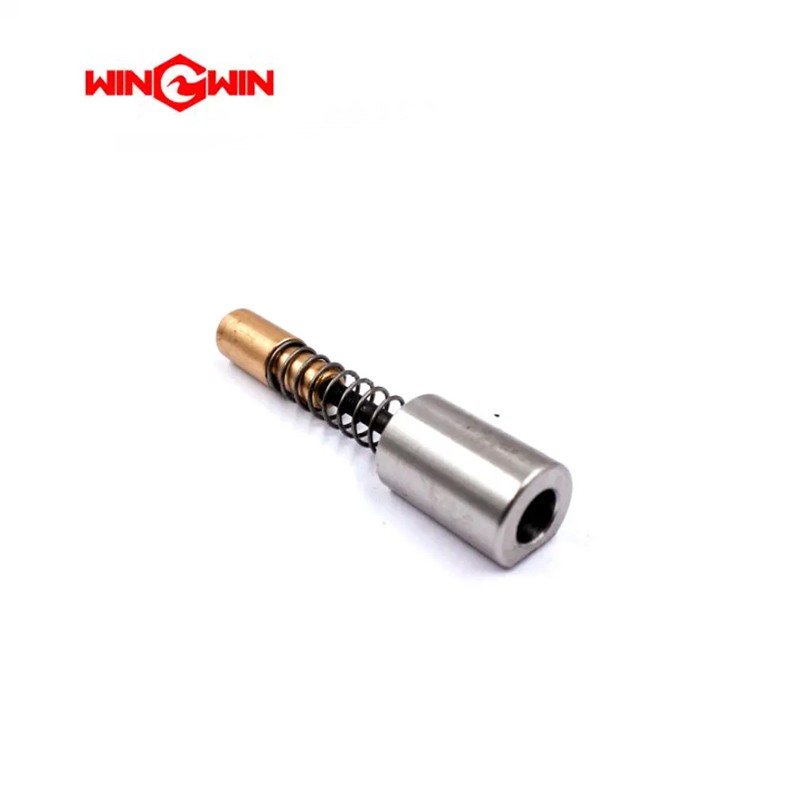

Table 12-8 Electronic Shift Assembly | |||
Item | Part Number | Description | Quantity |
1 | 20457897 | Firing Pin | 2 |
2 | 72106179 | Hydraulic Manifold Assembly | |
2.1 | 20499180 | Manifold | 1 |
2.2 | 10187052 | HP Relief Valve | 1 |
2.3 | 10187060 | LP Relief Valve | 1 |
2.4 | 10185585 | Solenoid Valve | 1 |
2.5 | 05122650 | Plug, ORB, #8 | 3 |
2.6 | 05104559 | Plug, ORB, #4 | 1 |
2.7 | 80085756 | Check Valve | 1 |
2.8 | 72106187 | Relief Valve | 1 |
2.9 | 72104336 | Ring Spacer | 1 |
3 | 20457264 | Actuator Assembly, Shift Sensor | 2 |
20458050 | Magnet Retainer | ||
20457372 | Plunger, Spring Guide | ||
20457501 | Nut, Spring Guide | ||
05203013 | Spring, Sensor | ||
05203021 | Spring, Sensor | ||
20493661 | Magnet | ||
4 | 20458290 | Shift Sensor Housing and Cable Assembly | 2 |
20457402 | Housing | ||
05202782 | O-Ring | ||
05202873 | O-Ring | ||
20459037 | Socket Head Screw, 10-24 x 1 | ||
20493669 | Cable, Electronic Sensor | ||
20493677 | Cord Connector | ||
5 | 20458941 | Pilot Shift and Main Valve Assembly | 1 |
20458173 | Hydraulic Spool | ||
20493695 | Shift Valve | ||
6 | 20493396 | Adapter, JIC/SAE, 1.0 x 1.0 | 2 |
7 | 95159513 | Socket Head Screw, 1/4-20 x 2 | 2 |
8 | 95119038 | Socket Head Screw, 3/8-16 x 2-1/4 | 4 |
9 | 95308508 | Hex Head Screw, 3/8-16 x 2-1/4 | 4 |
10 | 95277109 | Flat Washer, .38 | 4 |
The electronic shift assembly in a waterjet system is responsible for controlling the operation of the hydraulic intensifier pump,
specifically managing the shifting mechanism that ensures continuous high-pressure water flow. This assembly uses electronic controls
to automate the shifting process, enhancing efficiency, reliability, and precision in waterjet cutting operations.
Key Components of an Electronic Shift Assembly
1. Electronic Controller: The brain of the assembly, managing the shift operations and communicating with other system components.
It includes a microprocessor and software to control the shifting process.
2. Solenoid Valves: Electromagnetically controlled valves that regulate the flow of hydraulic fluid to shift the intensifier. They are actuated by signals from the electronic controller.
3. Sensors and Transducers: Measure various parameters such as pressure, position, and flow rate. These sensors provide real-time data to the electronic controller for precise control.
4. Actuators: Mechanical devices driven by the solenoid valves to physically shift the intensifier. They convert electrical signals into mechanical movement.
5. Wiring Harness: A set of wires and connectors that transmit electrical signals between the controller, sensors, solenoid valves, and actuators.
6. Feedback System: Provides real-time data on the shifting status, allowing the controller to make adjustments as necessary to ensure optimal performance.
7. User Interface: A display and control panel that allows operators to monitor the system's status, adjust settings, and perform diagnostics.
Maintenance Tips
Regular Inspection: Check the wiring harness, connectors, and electronic components for signs of wear, damage, or corrosion.
Sensor Calibration: Periodically calibrate sensors to ensure accurate readings and proper operation. Follow the manufacturer’s guidelines for calibration procedures.
Software Updates: Ensure that the electronic controller's software is up-to-date. Manufacturers may release updates to improve performance or address issues.
Clean Connections: Keep electrical connections clean and secure to prevent signal loss or interference.
Monitor Performance: Regularly check the system’s performance using the user interface. Look for any irregularities or error codes that may indicate a problem.
Troubleshooting Common Issues
Erratic Shifting: Could be due to faulty sensors or solenoid valves. Inspect and replace any malfunctioning components.
No Shift Operation: Check the power supply to the electronic controller and solenoid valves. Ensure that all connections are secure and that the controller is receiving the correct signals.
Pressure Fluctuations: May be caused by issues with the feedback system or incorrect sensor readings. Calibrate sensors and ensure that the feedback loop is functioning correctly.
System Errors:Use the diagnostics tools provided in the user interface to identify and troubleshoot specific error codes. Refer to the manufacturer's manual for detailed troubleshooting steps.
Actuator Failure: If the actuator is not responding, check for obstructions, proper alignment, and functionality of the solenoid valves controlling it.
Conclusion
The electronic shift assembly is a critical component in a waterjet system, ensuring the smooth and continuous operation of the hydraulic intensifier pump. Proper maintenance,
regular inspections, and timely troubleshooting of issues are essential to keep the system running efficiently and reliably.


